Low Voltage Electrical Design for La Cozii TK Condominium
Project Overview
| Item | Details |
|---|---|
| Project type | Bachelor's thesis / electrical building services design |
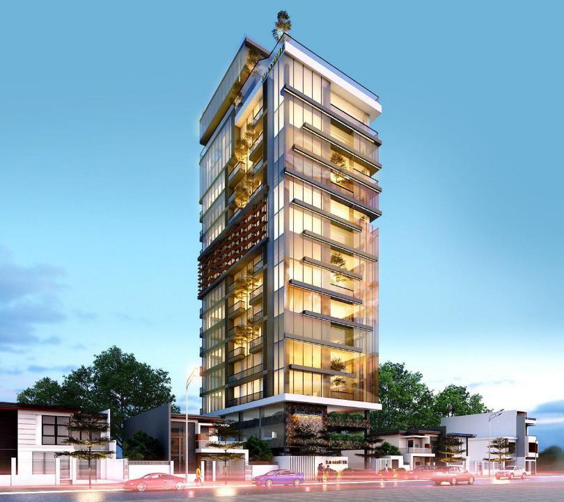
| Building | 18-storey residential and commercial condominium |
| Location | Tuol Kork District, Phnom Penh, Cambodia |
| Main focus | Low-voltage electrical supply and installation design |
| Standards and guides | IEC standard, Schneider Electrical Installation Guide 2018, and EDC design requirements |
| Software used | Microsoft Excel and EcoStruxure Power Design - Ecodial |
| Main design areas | Power demand, capacitor bank, transformer, generator, cable sizing, voltage drop, short-circuit current, and circuit breaker selection |
Problem Statement
Objectives
- calculating the maximum power demand of the project;
- correcting the power factor and sizing the capacitor bank;
- sizing the MV/LV transformer and backup generator;
- selecting conductor sizes for each circuit;
- calculating voltage drop and short-circuit current;
- selecting suitable circuit breakers and protection devices;
- comparing manual calculation results with EcoStruxure Power Design - Ecodial simulation results.
Design Methodology
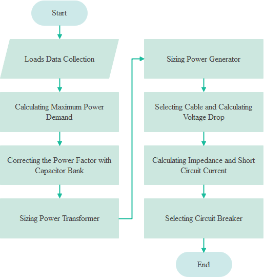
- collect the single-line diagram and load data;
- calculate the power demand from each load to the distribution boards;
- size the capacitor bank to improve the power factor;
- size the MV/LV transformer based on the corrected apparent power;
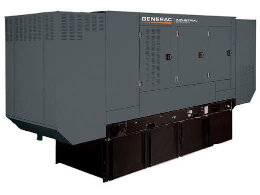
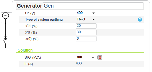
- size the generator based on emergency and critical loads;
- select the cable size by calculating the maximum load current;
- check the voltage drop and short-circuit current;
- select circuit breakers based on load current and fault current;
- verify the design using EcoStruxure Power Design - Ecodial.
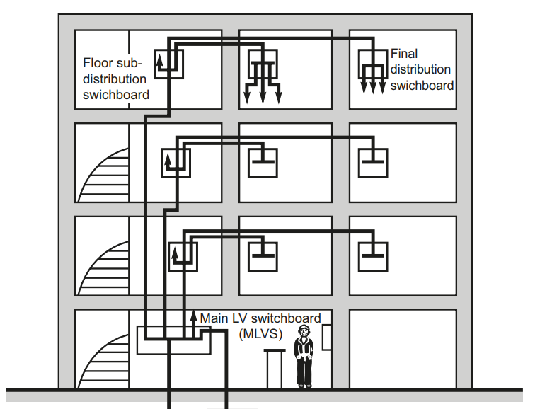
Building Electrical Distribution Concept
Main Equations Used
Installed powerEq. 2.1
Pinstalled = Σ(nᵢ × Pnᵢ)Pinstalled: total installed power [W]nᵢ: number of each load typePnᵢ: nominal power of each load type [W]
Estimated power demand of each load typeEq. 2.2
Pe = Ku × n × PnPe: estimated power demand [W]Ku: utilisation factorn: number of loadsPn: nominal power [W]
Maximum power demand in a circuitEq. 2.3
Pmax = Ks × ΣPePmax: maximum active power demand [W]Ks: diversity factorPe: estimated power demand of each load [W]
Reactive power demandEq. 2.4
Q = P × tan(cos⁻¹(PF))Q: reactive power demand [var]P: active power demand [W]PF: power factor
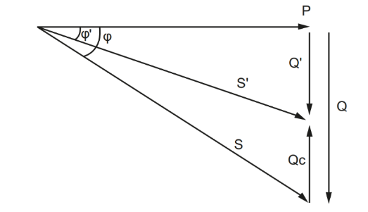
Required capacitor bank reactive powerEq. 2.8
Qc = P × (tan φ₁ - tan φ₂)Qc: required capacitor bank reactive power [var]P: active power demand [W]φ₁: phase angle before correctionφ₂: phase angle after correction
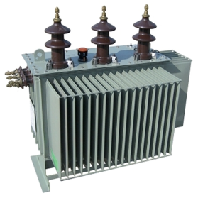
Transformer sizingEq. 2.9
STr = Safter correction × KeSTr: rated apparent power of transformer [kVA]Safter correction: apparent power after power factor correction [kVA]Ke: extension factor
Three-phase maximum load currentEq. 2.13
Ib = P / (√3 × U × PF × η)Ib: maximum load current [A]P: rated active power [W]U: phase-to-phase voltage [V]PF: power factorη: motor efficiency
Power Demand Calculation
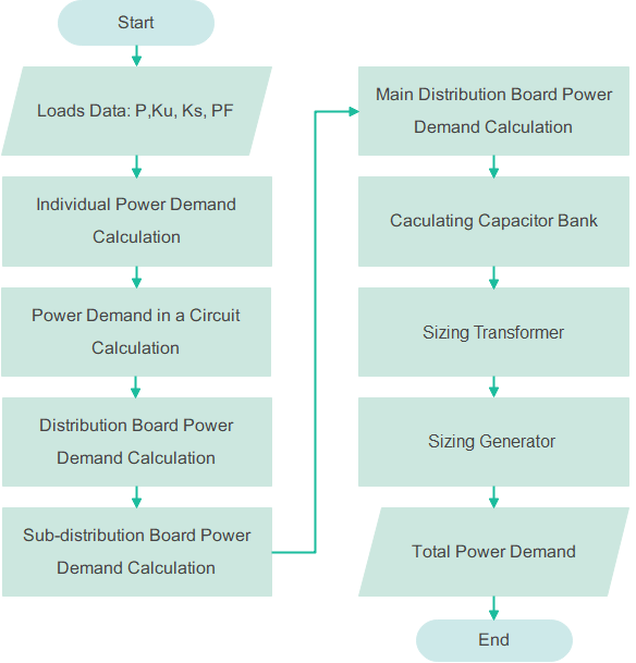
- estimating individual load demand;
- grouping loads into circuits;
- calculating demand for each distribution board;
- calculating sub-distribution board demand;
- calculating the main distribution board demand;
- determining the final active power, reactive power, apparent power, and average power factor.
Power Factor Correction
Transformer and Generator Sizing
Cable and Circuit Breaker Sizing
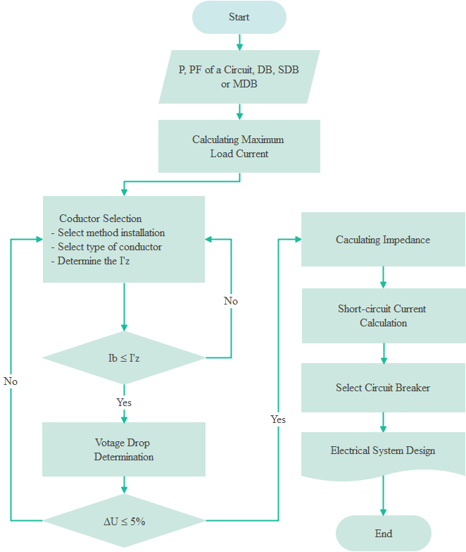
- the operating current of each circuit;
- the cable current-carrying capacity;
- the expected short-circuit current;
- overload and short-circuit protection requirements;
- coordination between upstream and downstream devices.
EcoStruxure Power Design - Ecodial Verification
Key Results
| Result area | Outcome |
|---|---|
| Total active power | approximately 392 kW |
| Total reactive power | approximately 291 kVAr |
| Total apparent power | approximately 488 kVA |
| System power factor before correction | approximately 0.80 |
| Maximum load current | approximately 704 A |
| Selected transformer | 630 kVA MV/LV transformer |
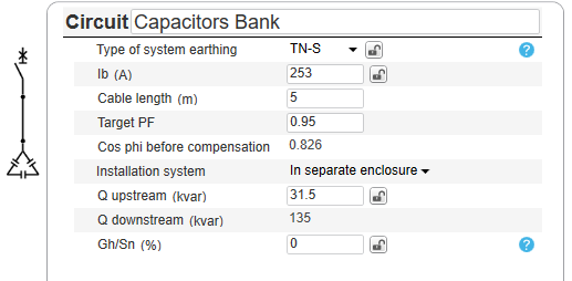
| Capacitor bank | 175 kVAR automatic capacitor bank |
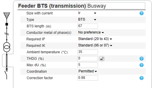
| Selected busway | 1000 A, approximately 67 m |
| Voltage drop | within the design limit, with one higher checked value around 1.87% |
| Ecodial comparison | small differences between Excel and Ecodial results due to calculation assumptions and software methods |
Discussion
What I Learned
References Used in the Thesis
- Schneider Electrical Installation Guide, 2018
- IEC 60364 Low-Voltage Electrical Installations
- Electricité du Cambodge Design Standard, 2007
- EcoStruxure Power Design - Ecodial calculation help
- Building Design and Construction Handbook